Introduction
Bridge Rectifier convers AC input into DC output. The rectification process is done by the junction diodes which are forward biased. When a junction diode is forward biased, it admits the current to flow through it. This application of junction diodes is mainly used in rectification. The Wheatstone Bridge system is used in Bridge rectifiers. Bridge rectifiers are also called Wave bridge rectifiers. It rectifies the waves also. Half-wave rectifiers and Full-wave rectifiers are examples of bridge rectifiers. There are many types of rectifiers but the Bridge rectifier is the more effective.
Bridge Rectifiers Definition
Bridge rectifiers effectively transforms the Alternating current into Direct current. A bridge rectifier circuit configuration consists of four or more diodes. Bridge rectifiers are another form of a full-wave rectifier.
Explore our latest online courses and learn new skills at your own pace. Enroll and become a certified expert to boost your career.
Bridge Rectifier Circuit
The bridge rectifier circuit is shown below. The Wheatstone Bridge system is applied in the four diodes. D1,D2,D3D1,D2,D3,and D4D4 diodes are set in the Wheatstone Bridge configuration.
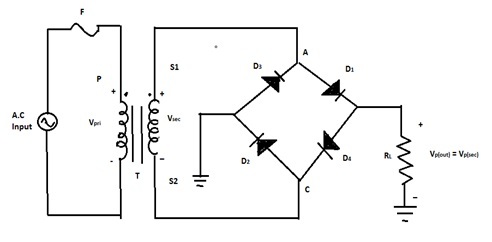
A and C ends are connected to the two ends of the secondary Transformer. The secondary ends of the transformer are denoted as S1S1 and S2S2. The AC signal is connected to the primary transformer. The positive half-cycle is conducted by the diodes D1D1 and D2D2. The negative half-cycle is conducted by the diodes D3D3 and D4D4. At the end of the two half-cycles, the load current flows through the circuit.
Vp(out)=Vp(sec)Vp(out)=Vp(sec)
Bridge Wave Rectifier
A Bridge Wave rectifier produces the output like a Bridge rectifier circuit. The wave rectifier also uses four separate diodes. It is a single-phase rectifier. Four separated diodes are linked with a closed-loop bridge circuit to get the required output. A special center-tapped transformer is not required for this Bridge wave rectifier. So, its cost and size needed are very less. It is the major advantage to use Bridge wave rectifiers. The AC signal is connected to the primary transformer. The positive half-cycle is regulated by the diodes D1D1 and D2D2. The negative half cycle is regulated by the diodes D3D3 and D4D4. A and C ends are connected to the two ends of the secondary Transformer. The secondary ends of the transformer are denoted as S1S1 and S2S2.
Construction
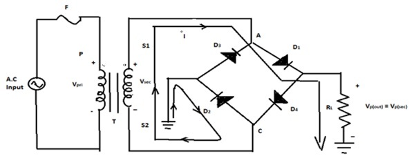
Bridge wave rectifiers have a configuration of the Bridge rectifier. D1,D2,D3D1,D2,D3, and D4D4 diodes are set in the Wheatstone Bridge configuration like a bridge rectifier. RLRL is the load resistance. A and C ends are connected to the two ends of the secondary Transformer. The secondary ends of the transformer are denoted as S1S1 and S2S2. The AC signal is connected to the primary transformer. The positive half cycle is regulated by the diodes D1D1 and D2D2. The negative half cycle is regulated by the diodes. At the end of the two half-cycles, the load current flows through the circuit.
Working
D1andD2D1andD2 diodes are forward biassed and current flows in the time of the positive half cycle of the input during this D3D3 and D4D4 are reverse biassed. Likewise, D3D3 and D4D4 diodes are forward biassed and current flow in the time of the negative half-cycle of the input during this D1D1 and D2D2 are reverse biassed. Therefore in the time of two input cycles current flows in the load resistance in a similar direction. So, the full-wave rectification process is done and the output of Direct Current is the wave developed across the load RLRL.
Characteristics Of Bridge Rectifier
Practical Diodes
In the positive half cycle and negative half cycle, the load resistor is always linked in series with both diodes. The output voltage is calculated when the diode drops are carried into account.
Vp(out)=Vp(sec)−1.4VVp(out)=Vp(sec)−1.4V
Peak Inverse Voltage (PIV)
If D1D1 and D2D2 diodes are forward biassed and D3D3 and D4D4 are checked for reverse bias. D1D1 and D2D2 have avoidable onward resistance and they can be pulled to be connecting wires because the diodes are considered perfect. The peak inverse voltage of diodes D3D3 and D4D4 is similar to the peak secondary voltage. Secondary voltage is similar to the output voltage.
Peakinversevoltage=Vp(out)Peakinversevoltage=Vp(out)
The peak inverse voltage value of the bridge diodes is lower than that needed for the center-tapped configuration.
The Average Value and Output Frequency
The full-wave bridge rectifier has a similar equation of average value and output frequency as the same as the full-wave rectifier because it produces a full-wave output.
Vdc=2VpπVdc=2Vpπ
fout=2finfout=2fin
Advantages
- The bridge rectifier has a soft Direct Current signal more than the output of the half-wave rectifier Direct Current.
- Input AC signals are used fully in bridge rectifiers. In the time of the positive half cycle and negative half cycle, electric current is allowed. But in the Half wave rectifier input AC signal is used partially. The rest of the AC signal is stopped. So there is a huge loss in AC input signals.
- During both positive and negative half-cycles, the electric current is enabled in the bridge rectifier. So, the output Direct current signal is nearly the same as the input Alternative Current signal.
Disadvantages
- There is a difficulty in forming the circuit configuration for bridge amplifiers.
- The bridge rectifiers consist of four diodes in comparison to other rectifiers.
- High power drops happen in bridge rectifiers. Because it consists of many diodes.
- There is an excessive voltage drop in the bridge rectifier. Because in the time of both half-cycle diodes are connected in series with load resistors. But in other rectifiers, during both half-cycles, one diode is used. So, voltage drop is less .
Conclusion
The instrument used to rectify the current is called rectifiers. The rectification process is done by the junction diodes which are forward biased. When a junction diode is forward biased, it admits the current to flow through it. There are many types of rectifiers. A Bridge Wave rectifier produces the output like a Bridge rectifier circuit. The wave rectifier also uses four separate diodes. It is a single-phase rectifier. Four separated diodes are linked with a feedback-control circuit to get the required output. This rectifier is cost-effective and the size required are less space.sticks, and baseball bats.
Leave a Reply