Introduction
Calculation of total circuit resistance is important to know the total amount of resistors used in both parallel and series resistors. Voltages can also be measured by significant resistive combinations. A circuit, associated with a resistor that helps in combining several parallels and series resistors is regarded as a resistor combination. Resistor network plays an important role. The method of calculating in which the resistance terms and values are calculated is simple and the same for both parallel and series combinations. The same value of current and resistors possess the same voltage.
Components of parallel and series resistor
Mixed resistor circuits are an important part of the resistor network. This helps in combining different parallel resistors. The total current value is to be estimated as well by following the formula of resistance measurement. In almost every aspect, a resistor in a particular and parallel connection is connected with the same nodes and possesses the same (La & Choi, 2020). This kind of structure is important to present the presence of many ways that ensure a smooth current flow between different resistors.
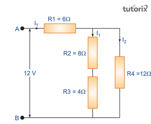
Figure 1: Resistors
As presented in the above graph, ITIT (total current) is extracted from a supply of electric 12V. In this graph, the value of R1R1 is presented as 6 ΩΩ. The value of R2R2 and R3R3 are also presented here that are 8Ω8Ω and 4ΩΩ. Both the R2R2 and R3R3 are connected to each other (Zhang et al. 2018). This connection is done in a series combination method. An equivalent resistance can be acquired by producing this connection. As a result of this 12Ω12Ω is calculated this is the addition result of 8Ω8Ω and Ω4Ω4. The input of the second resistor is important to be noted as it affects the current flow of the first resistor (Islam et al. 2020). A parallel circuit leads to a particular side of a resistor that is connected to the other resistors, even with a series resistor. At a certain time, more than one resistor is connected to each other in a parallel manner. That results in creating potential differences across every possible kind of resistor.
Explore our latest online courses and learn new skills at your own pace. Enroll and become a certified expert to boost your career.
Characteristics of a series circuit
In a series circuit, the same amount of current flows through all components. This helps in distributing the current flow accordingly and the connection within this circuit is strong in nature (Quynh et al. 2019). The structure of this type of circuit is simpler than the parallel circuit. In a series electrical circuit, all the components are arranged in a single line.
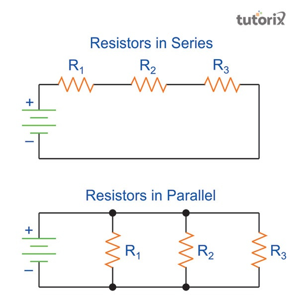
Figure 2: Resistors in series and parallel
The current flow in a series circuit is the same for all lines. The voltage across all other resistors is different in nature. In a series circuit, a single fault can cause to break down the whole current connection (Wang et al. 2019). The formula for calculating a total series resistor is Vt=V1+V2+V3.Vt=V1+V2+V3. In this equation, t refers to the number of resistors.
Characteristics of a parallel circuit
Besides series resorts, parallel resistors are another important circuit design. The parallel circuit design is more complex than the series circuit. This circuit is designed with many components (Ma, Chen & Ruan, 2020). Each of the components is connected to each other with a flowing current. Through the main source of current, this connection is made. A parallel circuit is also known as an electrical circuit. In this type of circuit, all associated components are properly arranged and settled in a proper way. In this type of circuit, in which resistors are arranged in a proper manner, the voltages are the same. In all resistors, the range is the same in nature.
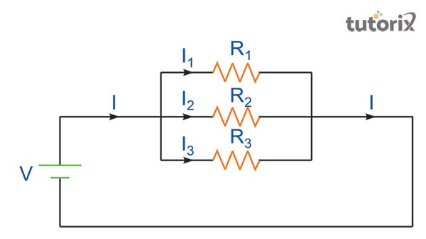
Figure 3: Structure of resistors
A parallel circuit is developed by arranging and connecting more than one component, in case of failure of one of its components, the other parts remain connected. The polarities of a parallel circuit are the same in nature (De Badyn & Mesbahi, 2019). This is a big advantage of using a parallel circuit. Each part of this type of circuit has an individual and independent circuit. The formula for calculating a parallel circuit is Vt=V1=V2=V3.Vt=V1=V2=V3. In this formula, Vt is the total value of voltage.
Conclusion
More than one electrical device is often connected with each other with the help of a circuit. These connections can be set by using a series and even in a parallel circuit method. Both of these types of circuits are important and significant in nature. Both of these components share a common node. The same range of current flows among these circuit ranges. In a parallel circuit range, two common nodes are available. The connection of these components is difficult but still important as a developed circuit.
Leave a Reply